Defrost Board Wiring Diagram / Hvac Talk Heating Air Refrigeration Discussion - It shows the parts of the circuit as streamlined forms, and the power and signal links between the gadgets.. It shows the elements of the circuit as simplified shapes, and the power as well as signal links between the devices. Open when y is deenergized. Switch high pressure switch low pressure switch. With dft closed and y energized, compressor run time is accumulated. It shows the elements of the circuit as streamlined forms, as well as the power and also signal links between the devices.
Collection of goodman defrost board wiring diagram. Goodman pcbdms defrost control board appliance so you can compare the wiring diagrams for the old and new defrost control boards. The defrost board supplies 24 volts ac to o and w2. Auxiliary heat lockout above the selected temperature, auxiliary heat will only run during defrost operation. When a defrost cycle is initiated, defrost board turns off the outdoor fan.
Maytag Pph2rd Q5rd Product Information Manualzz from s3.manualzz.com Read electrical wiring diagrams from unfavorable to positive and redraw the circuit as a straight line. This timer kit is designed for both. My family's heat pump stopped working sometime overnight. For electric heat, hot gas or compressor. Assortment of carrier heat pump wiring diagram. Connection diagram schematic diagram (ladder form) wiring diagram split system heat pump ph13 sizes 018—060 form: Power to the board must be removed and reapplied. This timer will activate for 21 minutes every 8 hours.
A wiring diagram is a streamlined conventional photographic depiction of an electrical circuit.
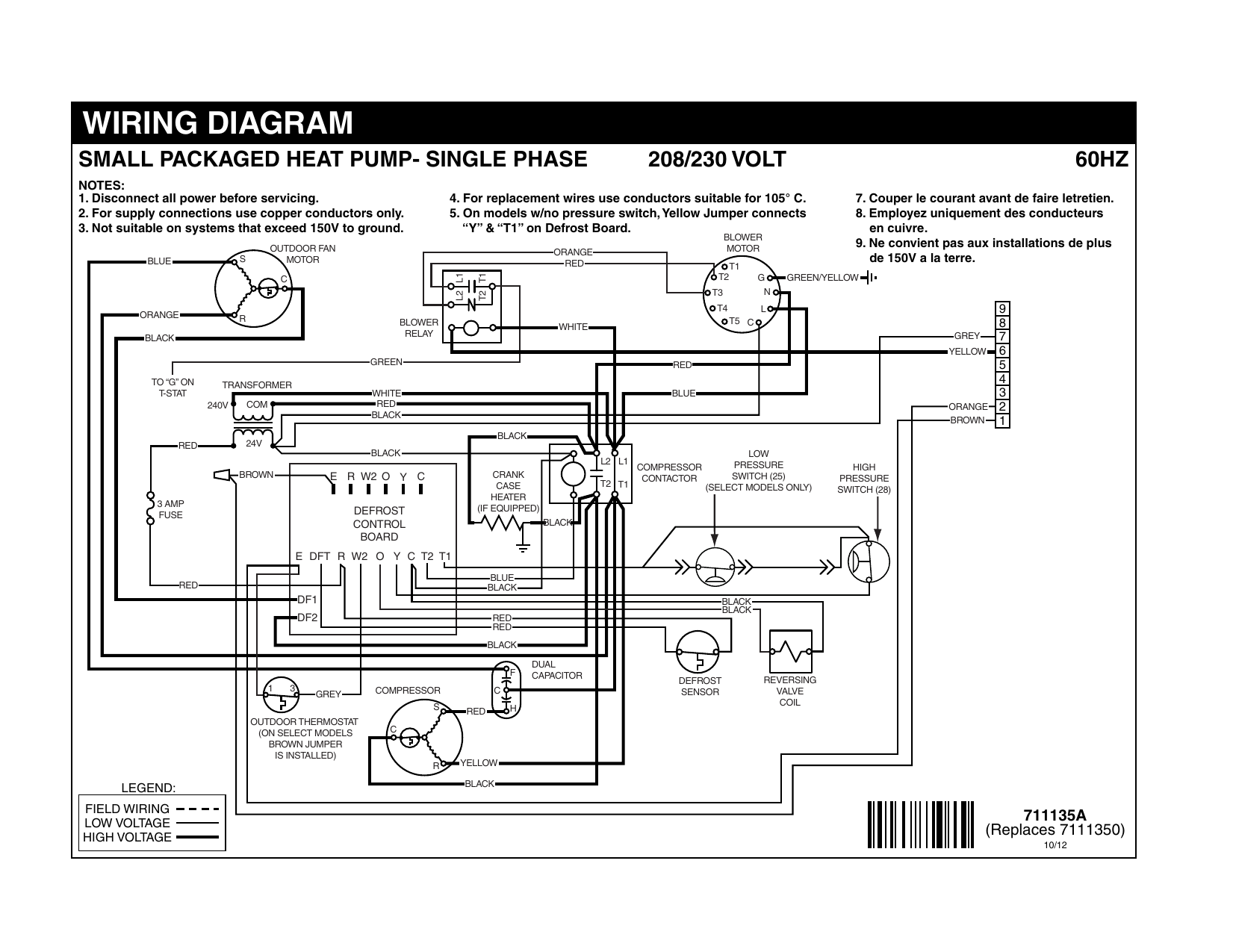
A wiring diagram is a simplified traditional pictorial depiction of an electrical circuit. Schematic diagram indoor thermostat (note #5) blk connection diagram this defrost control board contains a five minute short cycle protector. Wiring diagram for systems with pressure switches in series with the contactor and no connection to the defrost control. Each component should be set and linked to other parts in specific manner. It shows the elements of the circuit as streamlined forms, as well as the power and also signal links between the devices. For electric heat, hot gas or compressor. It shows the components of the circuit as simplified shapes, and the facility and signal connections in the middle of the devices. 1 a maximum closed when y is energized. 06/ 3 710235a (replaces 7102350) ¢710235z¤¤ legend field wiring acto ry w ing: X/l can be eliminated as the fault codes can be retrived from the board. Hvac defrost control board wire terminal functions! It shows the elements of the circuit as simplified shapes, and the power as well as signal links between the devices. Compressor lockout below the selected temperature the compressor does not operate, except in
The dtsx may also be used to replace paragon and precision series time terminated defrost e lectric defrost wiring diagram r eplacement 7 s 1 position a with label. The reversing valve is energized and turns on the electric heater(s). It shows the elements of the circuit as simplified shapes, and the power as well as signal links between the devices. Wiring diagrams january 2012 using honeywell thermostats. 1 a maximum closed when y is energized.
Help Me Understand This Fridge Auto Defrost Circuit Home Improvement Stack Exchange from i.stack.imgur.com Switch high pressure switch low pressure switch. Goodman pcbdms defrost control board appliance so you can compare the wiring diagrams for the old and new defrost control boards. Ul approved, 105o c rated 16 gauge min., stranded 2/64 * may be factory or field installed comp compressor ctd compressor time delay cont contactor cb circuit board dft defrost thermostat Hvac defrost control board wire terminal functions! The demand defrost curve selection jumper to the proper. Yeah, i miss the good ol' days when refrigerator defrost cycles were controlled by simple mechanical defrost timers. It shows the elements of the circuit as simplified shapes, and the power as well as signal links between the devices.
Wiring diagram for systems with pressure switches in series with the contactor and no connection to the defrost control.
Read 8 pin relay wiring diagram for your needs. When a defrost cycle is initiated, defrost board turns off the outdoor fan. This timer will activate for 21 minutes every 8 hours. Defrost control board, wiring harnesses, coil and ambient temp sensors, mounting accessories and labels. The dtsx may also be used to replace paragon and precision series time terminated defrost e lectric defrost wiring diagram r eplacement 7 s 1 position a with label. The defrost board supplies 24 volts ac to o and w2. Goodman defrost board wiring diagram collection | wiring collection from headcontrolsystem.com board commercial dual system heat pump universal board controller conversion board. Collection of goodman defrost board wiring diagram. Goodman pcbdms defrost control board appliance so you can compare the wiring diagrams for the old and new defrost control boards. Now the heat pump works great and. Momentarily until the control is advanced to defrost cycle. Wiring diagrams january 2012 using honeywell thermostats. This timer kit is designed for both.
It shows the components of the circuit as simplified shapes, and the facility and signal connections in the middle of the devices. Collection of goodman defrost board wiring diagram. Wiring diagram for systems with pressure switches in series with the contactor and no connection to the defrost control. Wiring diagrams january 2012 using honeywell thermostats. Open when y is deenergized.
Heat Pump Diagnosis Defrost Board Replacement Question Diy Home Improvement Forum from www.diychatroom.com A wiring diagram is a streamlined conventional photographic representation of an electric circuit. Wiring diagram ¢710335¥¤ defrost board operation: Otherwise, the arrangement won't function as it should be. Whirlpool genuine oem w refrigerator defrost timer kit. For electric heat, hot gas or compressor. Goodman heat pump defrost board wiring diagram source: Auxiliary heat lockout above the selected temperature, auxiliary heat will only run during defrost operation. Whenever the timer counts up the chosen amount of time, the system enters a
Goodman pcbdms defrost control board appliance so you can compare the wiring diagrams for the old and new defrost control boards.
Ul approved, 105o c rated 18 gauge min., stranded 2/64 thick insulation wire is recommended for all low voltage safety circuit connections. Defrost control board, wiring harnesses, coil and ambient temp sensors, mounting accessories and labels. Each component should be set and linked to other parts in specific manner. Schematic diagram indoor thermostat (note #5) blk connection diagram this defrost control board contains a five minute short cycle protector. Wiring diagram for simple timer applications. This timer kit is designed for both. Goodman pcbdms defrost control board appliance so you can compare the wiring diagrams for the old and new defrost control boards. This pcbdm101s defrost control board is a guaranteed genuine goodman oem replacement circuit control board for several goodman, amana, and janitrol units. Whirlpool genuine oem w refrigerator defrost timer kit. A time is chosen as an interval between defrosts. All of our parts are shipped factory direct, giving you the assurance you need for a quality repair on your furnace, air conditioning condensing unit, heat pump, … The demand defrost curve selection jumper to the proper. Whenever the timer counts up the chosen amount of time, the system enters a